Our Projects
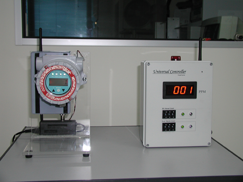
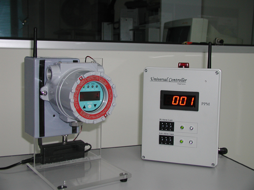
Wire/wireless universal controller, taking input 0-2V, 20mA with variable high-low limit setting
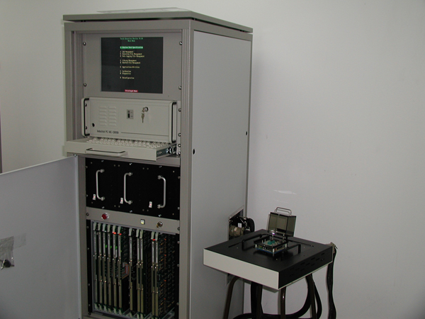
System upgrade of HP-based testers’ operating system (OS) from MS-DOS to Windows 98/2000/XP, as well as the data bus from ISA bus to PCI bus.
Controller
System Upgrade
Features of AOT Upgrade System January 31, 2007
- Completely Windows-based and compatible with Windows 98/2000/XP
- Control card is PCI bus Plug and Play capability
- User Interface for System cards
- Interactive controls for immediate setup test results
- Automatic Program code generation
- On-line editing during coding / Off-line editing using text files
- Debug features, Summary and Data logging Supported
Installation:-
- Click on the ‘AddtDemo.exe’ to unzip.
Enter ‘C:\AddtDemo’ as the directory to unzip.
Go to that directory. - Click the ‘Setup.exe’ icon and follow the instructions to install the Demo Software. (Note: Re-booting is required if the instruction says so.)
This Demo simulates the function of the various cards of the AOT. It will not operate in the AOT System.
Basic Operation:-
- Click on the ADDT icon and the System will appear.
- To load an existing program, click on the [Load] button and select from the ‘Data’ directory.
- To start the Test, click the [Start Test] button on the screen or the Push button of the control box.
Pass/Fail Bin will appear at the end of the Test. - To see the test data of the test click on the [Debug] button and then item(3)
- To repeat the test continuously, click the [Looping] button and then item(3)
- To stop the test, click the [Manual] button.
- To get the summary, click the [Summary] button. Then select also [Print] or [Save]
- To datalog, click the [Datalog] button and select one of the 3 modes.
Setup:-
- Click the [Setup] button. (This is for interactive programming and also code generation.)
- Click the appropriate buttons to set the Test Description, Parameters, VI Sources, Matrix/Test Head Relays, Formulas, Delay and Fail/Pass Binning.
- For each set up, click the [Keep] button in the Page No. section.
- Click the [Seq End] button to signify the end of the test sequence.
- Click the [Keep] button of the Test No. section. This will complete a particular test setup.
- To set up another test setup, repeat steps 2 to 5.
- To save the whole test program, click the [Save] button, enter a name as the destination. It will be stored in the ‘Data’ directory.
- To run the test program, refer to step 2 of Basic Operation onwards.
- Click on the [Set Bin] button to change the colour of the Bins and the default bin no.
Calibration and Configuration:-
- Click on the [Calibrate] button. Click on the [Cal] button and enter the Calibration Board’s data.
- Click on the [VMU] button then click n the [Cal] button to calibrate it.
- Click on the [V/I] sources and its [Cal] button one at a time to complete their calibration respectively.
- Click on the [Configure] button to select the VMU/VI Sources/DSG to Line for the System.
Other Features:-
- During interactive operation, the System will automatically show the program code at the lower display area.
It will prompt for whether the current setup is to be save, click [Yes]/[No] to confirm. - Program codes can be Deleted/Inserted/Override during on-line editing.
- During Off-line editing, the file can be loaded into ‘Notepad’ and using cut and paste method to change the commands set.
- Parameters can be declared any where in the test sequence except before their use in storage or calculation.
Variables and just declared while constants have to be given values in decimals. - Formula are process in the RPN e.g Hfe = (Ic * 1000) / Ib, where the ( ) represents the nesting of the calculation.
- The System will update the time display when idle.
- The default directories are ‘C:\ADDT’, ‘C:\ADDT\DATA’, ‘C:\ADDT\LOG’, ‘C:\ADDT\SUMMARY’ and ‘C:\ADDT\SYSTEM’.